Concept Notes Videos 261. D what is the purpose of the soft iron core used in making an electromag - eanswersin.
What Is An Electromagnet Describe The Construction And Working Of An Electromagnet With The Help Of A Labelled Diagram Sarthaks Econnect Largest Online Education Community
Draw a labelled diagram to make an electromagnet from a soft iron bar.
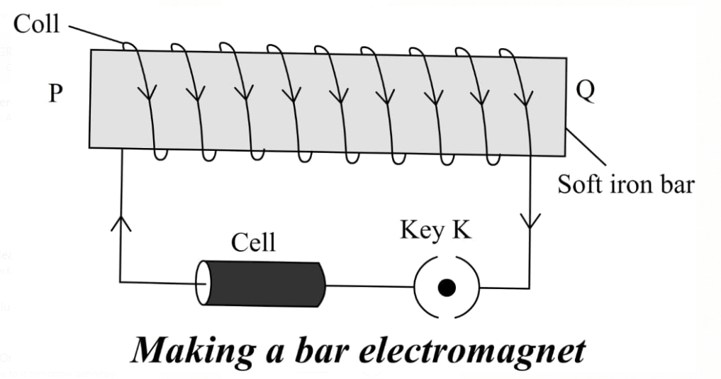
Labelled diagram to show how an electromagnet is made. Take a soft iron bar PQ and wind a thin insulated copper wire around the bar. A What is electromagnetb List any of its two usesC Draw a labelled diagram to show how an electromagnet is maded What is the purpose of the soft iron core used in making an electromagnet26. Magnetic Effects of Electric Current.
When key K is closed current passes through the winding of the coil and the bar becomes a magnet. What precaution would you observe while making it. 1 Answer 1 vote.
CISCE ICSE Class 10. Draw a Labelled. Mark the polarity at its ends in your diagram.
Advertisement Remove all ads. The circuit diagram is shown in figure. A simple electromagnet comprises a length of wire turned into a coil and connected to a battery or power supply.
B list any of its two uses. B list any of its two uses. Dear Student An electromagnet.
The near moint of the. Connect a cell or a battery B and a key K in series between the ends of the coil. A Draw a labelled diagram to show how electro magnet is made bWhat is the from HISTORY 098 at New Horizon Scholars School Neo Kids.
Question Bank Solutions 26084. C draw a labelled diagram to show how an electromagnet is made. Draw a labeled diagram to show how electro magnet is made Share with your friends.
A A current carrying solenoid is called an electromageet when soft iron is placed inside a solenoid carrying current the soft iron piece behaves like a magnet so long as electric current passes through it. Correct answer to the question. We use an iron nail battery copper wire to make the circuit.
Magnetic effects of electric current. A what is an electromagnet. The main components of this DIY Magnetic levitation circuit are the Hall effect sensor and MOSFET transistor and an electromagnetic coil.
Draw a labeled diagram to show how electro magnet is made - Science - Magnetic Effects of Electric Current. What Precaution Would You Observe While Making It. Answered Oct 12 2020 by Jaanvi01 580k points selected Oct 12 2020 by Kaanta.
Correct answer to the question. Draw a labelled diagram to show how an electromagnet is made. Mark the Polarity at Its Ends in Your Diagram.
Click hereto get an answer to your question Draw a labelled diagram to show how an electromagnet is made. To make a fiar or I shaped electromagnet. Mark the polarity at its ends in your diagram.
Draw a labelled diagram to make an electromagnet from a soft iron bar. A person is suffering from hypermetropia. Concept Notes Videos 248.
Question Bank Solutions 20334. Share It On Facebook Twitter Email. CBSE CBSE English Medium Class 10.
Draw a labelled diagram to show how an electromagnet is made. Draw a Labelled Diagram to Show How an Electromagnet is Made. You can make an electromagnet stronger by doing these things.
A soft iron bar as an electromagnet draw labelled diagram to show how class 12 physics cbse be transformed into gr7 technology conditions permanent what is describe the components of circuit energy. Draw A Labelled Diagram To Show How An Electromagnet Class 12 Physics Cbse Draw A Labelled Diagram To Show How Electro Magnet Is Made Science Magnetic Effects Of Electric Cur 9600603 Meritnation Com Draw A Labelled Diagram To Show How An Electromagnet Is Made Brainly In Draw A Circuit Diagram To Show How Soft Iron Piece Can Be Transformed Into An Electromagnet. B Below is the labelled diagram showing how an electromagnet is made-.
Awhat is an electro magnet blist any two uses of it cdraw a labelled diagram to show how an electromagnet is made dwhat is the purpose of the soft iron core used in making an electromagnet - Science - Magnetic Effects of Electric Current. A what is an electromagnet. Draw a Labelled Diagram to Make an Electromagnet from a Soft Iron Bar.
Mark the polarity at its ends in your diagram. An electromagnet is that in which a magnetic material such as soft iron is placed inside the solenoid and on applying the current through solenoidit is magnetized. C draw a labelled diagram to show how an electromagnet is made.
The magnet so formed is electromagnet. Draw A Labelled Diagram To Make Soft Iron Bar As An Electromagnet Studyrankersonline Draw A Labelled Diagram To Show How An Electromagnet Is Made Brainly In Draw A Labelled Diagram To Show.
Describe an activity to show that a current carrying conductor placed perpendicular to the magnetic field experiences a force. The electromagnetic spectrum is comprised of all frequencies of electromagnetic radiation that propagate energy and travel through space in the form of waves.

Draw A Labelled Diagram To Show How An Electromagnet Is Made
Draw a labelled diagram to show how an electromagnet is made.

Draw a well labelled diagram to show how an electromagnet is made. Asked Feb 22 2019 in Physics by Aksat 693k points. Thisdiagram also includes background information which may be useful. When the switch is pushed on the circuit gets completed and the current starts flowing through the U-shaped electromagnet which creates a magnetic field.
List any two uses. An electromagnet can be defined as a magnet which functions on electricity. B Draw a labelled diagram to show how an electromagnet is made.
By interrupting current in the coils a sudden high voltage is set-up across the gap. The first part of the word electro sounds like electricity. Note - R represent red light and G represents green light 5 marks Fig.
Describe with the help of a labelled diagram an activity to demonstrate the force acting on a current carrying conductor due to magnetic field. CBSE 2014 2015 Answer. Mark the polarity at its ends in your diagram.
Draw a labelled diagram to show how an electromagnet is made. But this is also an advantage of the electromagnet over a. 1 when the switch is closed explain the operation of the CR coil.
Draw the diagram of an electric motor and label the following parts. The second part of the word magnet is what it sounds likea magnet. An electric motor that works on direct current unidirectional current is called a DC motor.
If you are looking for example diagrams of the electro-magnetic spectrum there are a number of these on the internet. Answer 1 of 1. Shorter wavelengths with higher frequencies make up the optical spectrum.
So an electromagnet is a magnet that is created by electricity. Fix a horse shoe magnet on the top of the table. 1 bar or I shaped magnet and 2 horse shoe or U shaped magnet.
D List two ways of increasing the strength of an electromagnet if the material of the electromagnet is fixed. If you type the words electro magnetic spectrum diagram wavelength in a search engine you will also find several links to articles and diagrams which should also help you to create your own. Draw a labelled diagram to make an electromagnet from a soft iron bar.
Draw a labelled diagram to show the forces acting on a skydiver falling with a constant velocity. Q18 Draw a neat and labelled diagram of an electric bell and describe its working. What is a DC motor.
The spheres are connected to an induction coil. Well an electromagnets name helps tell us what it is. Answer verified by Toppr.
To make a fiar or I shaped electromagnet. The accompanying diagram will help you understand the working in a clear manner. A What is an electromagnet.
2 below is a light sensor that we of Hoht sensor is. If the current flow is cut the property of magnetism ceases to exist. Take a soft iron bar PQ and wind a thin insulated copper wire around the barConnect a cell or a battery B and a.
Write the word electromagnet on the classroom board for students to see Lets break it down. C State the purpose of soft iron core used in making an electromagnet. Figure shows Hertz s experimental set-up used for producing electromagnetic wavesTwo large metal plates P and P are connected to metal sphere S and S.
Usually the electromagnets are made in two shapes. Asked Dec 22 2018 in Class X Science by navnit40 -4939 points Draw a labelled diagram to make an electromagnet from a soft iron bar. A horizontal metre stick is in equilibrium when a weight of 8 N hangs from the 10 cm mark a weight of 12 N hangs from the 60 cm mark and an unknown weight X hangs from the 82 cm mark.
Draw a neat labelled diagram of an electric motor. Application Using Electromagnetic Spectrum. Unlike a permanent magnet the strength of an electromagnet can be changed by changing the amount of electric current that flows through it.
Click to find video solution. An electromagnet consists of a coil wound around an iron piece and connected to a battery. Click hereto get an answer to your question Draw a labelled diagram to show how an electromagnet is made.
A Draw a circuit diagram to show how a soft iron piece can be transformed into an electromagnet. B 1 and B 2 Carbon brushes Ba Battery. 5 marks In the hardwired relay control circuit of Fig.
I Draw a well-labeled diagram of an electromagnetic control relay. Asked Aug 28 2018 in Physics by AbhinavMehra 225k points magnetic effects of. Electromagnetic spectrum is nothing but a group of frequencies that are categorized according to the frequency ranges they occupy and exhibit certain uses on account of these ranges known as a spectrum.
Longer wavelengths with lower frequencies make up the radio spectrum. This voltage ionises the air in the gap which produces oscillating current in the gap SS. NCERT solution for class 7 science chapter 14 Electric Current and its effects is a crucial study material to score good marks in CBSE class 7 science examination.
This chapter has good weightage of marks allotted hence students are advised to study this chapter thoroughly. Mark the polarity at its ends in your diagram.
Mention any other purpose served by this part other than nutrition. Describe the process of nutrition in Draw labelled diagrams to show the various steps in the nutrition in Amoeba.
A Draw A Diagram To Show The Nutrition In Amoeba And Label The Parts Used For This Purpose Sarthaks Econnect Largest Online Education Community
Holozoic nutrition in amoeba takes place in the following steps.

Draw labelled diagram to show the various steps of obtaining nutrition in amoeba. Let us have a clear picture of the different processes involved in the nutrition of amoeba. Draw labelled diagrams to show the various steps in the nutrition in Amoeba. Nutrition in Living Organisms.
B Name the glands associated with digestion of starch in human digestive tract and mention their role. Amoeba has no mouth for ingestion of food. What does it mean.
The food in the food vacuole is digested by. Describe the process of nutrition in Draw. Draw labelled diagrams to show the various steps in the nutrition in Amoeba.
Describe the process of nutrition in amoebaDraw labelled diagram to show that various steps of nutritions in amoeba. A Draw diagram to show the nutrition in Amoeba and label the part used for this purpose. Amoeba follows holozoic nutrition.
The pseudopodia is one of the most important aspects to an amoeba. A Describe the process of nutrition in Amoeba. The food is engulfed with little water to form a food vacuole.
A Describe the process of nutrition in Amoeba. Nutrition in amoeba involves the following steps i Ingestion. B What is the mode of nutrition in Amoeba known as.
C What is the process of obtaining food by Amoeba called. It does this using its pseudopodia and forms a food vacuole. Mention any other purpose served by this part other than nutrition.
This process of nutrition in Amoeba is called Endocytosis. B What is the mode of nutriti. It ingests the food by using its pseudopodia.
Amoeba ingests food along with a little amount of the surrounding water. C What is the process of obtaining food by Amoeba called. B What is the mode of nutrition in Amoeba known as.
The main components of an amoebas diet are bacteria and algae. Following are the steps involved in the nutrition in Amoeba. A Nutrition in amoeba.
Describe the process of nutrition in Draw labelled diagrams to show the various steps in the nutrition in Amoeba. Draw labelled diagrams to show the various steps in the nutrition in Amoeba. A Describe the process of nutrition in Amoeba.
What does it mean. Amoeba ingests food along with a little amount of the surrounding water. Following are the steps involved in the nutrition in Amoeba.
Find an answer to your question a Describe the process of nutrition in Amoeba. Draw the diagram of sectional view of human heart and on it name and label. A Describe the process of nutrition in Amoeba.
Describe the process of nutrition in Draw labelled diagrams to show the various steps in the nutrition in Amoeba. Draw labelled diagrams to show the various steps in the nutrition in Amoeba. Draw labelled diagrams to show the various steps in the nutrition in Amoeba.
A Draw diagram to show nutrition in Amoeba.
Asked Aug 1 2019 in Physics by Rk Roy 637k points jee. I Draw a labelled ray diagram showing the image formation of a distant object by a refracting telescope.
Draw Ray Diagram To Show The Formation Of Images When The Object Is Placed In Front Of A Concave Mirror Converging Mirror Between Its Pole And Focus Studyrankersonline
The focal length of one lens is 20 times that.
Draw a labelled ray diagram to show the image formation in each case. Ii Write three distinct advantages of a reflecting type telescope over a refracting type telescope. Advertisement Remove all ads. C State three characteristics of the image.
A Draw a labelled ray diagram to shwo the formation of image in a convex mirror when the object is at infinity. Derive the expression for its magnifying power in normal adjustment. C Draw diagram to show how a convex mirror can be used to give a large field of view.
Draw a labeled ray diagram to show the formation of image of an object by a convex mirror. Ii Write three distinct advantages of a reflecting type telescope over a refracting type telescope. A i Draw a labelled ray diagram to show the formation of image in an astronomical telescope for a distant object.
Draw a ray diagram to show the formation of image of an object placed at the centre of curvature of a concave mirror. Ii The sum of focal lengths of the two lenses of the two lenses of a refracting telescope is 105 cm. State the signs and values of magnifications in the above mentioned cases i and ii.
Draw labelled ray diagram to show the formation of the required image in each of the above two cases which of these mirror could also form a magnified and real image of the object state the position of objects for which his could happen. List two such rays and state the path of these rays after reflection in case of concave mirrors. Due to these reasons the image.
State the position size and nature of the image. Draw a ray diagram to show the formation of image of an. Ii Write three distinct advantages of a reflecting type telescope over a refracting type telescope.
B spreading of the eye-sphere. Ii anywhere in front of a concave lens. I Which lenses should he used as objective and eyepiece.
B A convex lens of focal length 10 cm is placed coaxially 5 cm away from a concave lens of focal length 10 cm. What happens to the image when the object is moved away from the mirror gradually. B A convex lens of focal length 10 cm is placed coaxially 5 cm away from a concave lens of focal length 10 cm.
A SOLAR FURNANCE BREAR VIEW MIRROR - Science - Light - Reflection and Refraction. Iii at 2F of a convex lens. If an object is.
Draw a ray diagram in each of the following cases to show the formation of image when the object is placed. Myopia or shortsightedness. Deduce the expression for its magnifying power when the final image is formed at infinity.
A Draw a labelled ray diagram to show the formation of image of an object by a convex mirror. A Draw a labelled ray diagram showing the formation of a final image by a compound microscope at least distance of distinct vision. Mark clearly the pole and focus of the mirror in the diagram.
Mark clearly the pole focus and centre of curvature on the diagram. A i Draw a labelled ray diagram to show the formation of image in an astronomical telescope for a distant object. Question Bank Solutions 6884.
Draw a ray diagram to show the formation of image of an object placed at the centre of curvature of a concave mirror. I between optical centre and principal focus of a convex lens. Use these two rays and draw ray diagram to locate the image of an object placed between pole and focus of a concave mirror.
State the position size and nature of the image. B A convex lens of focal length 10cm is placed coaxially 5cm away form a concave lens of focal length 10cm. B State three characteristics of the image formed in this case.
Draw labelled ray diagrams to show the formation fo image in each fo the following cases. Draw a labeled ray diagram showing the image formation of an astronomical telescope in the normal adjustment position. To construct a ray diagram we use two rays which are so chosen that it is easy to know their directions after reflection from the mirror.
Mark clearly the pole and focus of the mirror in the diagram. A Draw a labelled ray diagram to obtain the real image formed by an astronomical telescope in normal adjustment position. State three characteristics of the image.
B The total magnifica. A Draw a labelled ray diagram to shwo the formation of image in a convex mirror when the object is at infinity. B State three characteristics of the image formed in this case.
Write two basic features which can distinguish between a telescope and a compound microscope. B What happens to the image when the object is moved away from the mirror gradually. CISCE ICSE Class 8.
Nature - A real inverted image of the same is formed at the centre of curvature. Draw a labelled ray diagram to show the image formation by an astronomical telescope. C Draw diagram to show how a convex mirror can be used to give a large field of view.
Position of image - Image formed is at C. This defect is due to a decrease in focal length of the eye lens. A i Draw a labelled ray diagram to show the formation of image in an astronomical telescope for a distant object.
Mark clearly the pole focus and centre of curvature on the diagram. B You are given three lenses of power 05 D 4 D and 10 D to design a telescope. Concept Notes Videos 272.
Myopia is the defect of eye in which a person can see only nearby objects but fails to see the far away objects distinctly. Define its magnifying power.
ThD1 Draw a neat diagram showing different zones of candle flame and label itsdifferent parts2 Get the answers you need now. Label the zone which contains.

How To Draw And Label Candle Flame Youtube
No comments draw a diagram showing the different zones of candle flame.

Draw a neat labelled diagram to show different zones of a candle flame. Different zones of a candle. Draw a diagram showing the different zones of candle flame. Innermost zone or the luminous zone.
B At finite distance from the mirror. All these three zones have different colour and temperatures. Draw a particle.
Dear student Definition-A flame is. Explain the different zones of a flame with the help of a neat and well labelled diagram. 5 There are three zones in a candle flame.
The first zone is called the Outer zone. 64k 1318k 303. Watch the video and please be kind enough to thumbs up my vid.
Characteristics of these zones are tabulated as follows. In a candle flame a quarter of the energy created is released as heat. Explain the different zones of a flame with the help of a neat and well labelled diagram.
Click to rate this post. Outer zone or the non-luminous zone. Candle Flame Different Zones.
How much of wood is required to produce 360000 kJ of heat energy. Submitted by on Sat 05122020 - 0916 Sat 05122020 - 0916. A flame consist of three zonesThese are Innermost zonemiddle zoneouter zoneThe three zones of a flame have different colours and different temperature.
The second zone is called the Middle zone. The innermost zone is the zone which is formed just around the wick of the candle flame as the candle burns. The bottle containing sulphuric acid is struck with a knob.
Afaanshaikh042 afaanshaikh042 25012021 Science Secondary School answered Th D1 Draw a neat diagram showing different zones of candle flame and label its different parts. A Which zone is luminous and why. This is the non.
This zone is blue in colour. The different zones present in a candle flame are as follows. 1 on a question Explain the four zones of the candle flame with the help of neat and well labelled diagram.
It is also known as dark zone of the flame. 1 The Innermost zone of a flame is dark or blackIt consist of hotunburnt vapours of the combustible materialIt is the least hot part of the flameIt is the coldest part of the flame. Draw a neat labelled diagram showing forces acting on the meniscus of water in a capillary tube.
This is the non. It is known as luminous zone. It contains unbumt vapours of wax.
2 1 See answer afaanshaikh042 is waiting for your help. The thin outermost zone of the flame is blue in colour and complete combustion takes place. If you look closely at a candle flame youll see a blue area at the base of the flame.
Draw a neat labelled diagram showing different layers of the Earths atmosphere. Draw neat labelled diagram and explain the parts of candle flame Share with your friends. Draw A Labelled Diagram Of A Candle Flame And Explain What Happens In Each Zone.
Jul 4 2019 - A beautiful drawing of Candle flameAnd it will teach you to draw the Candle flame very easily. It consists of hot unburnt vapours of the combustible material. Calorific value of wood is 18000 kJkg.
The innermost zone is the dark zone. Explain the different zones of a flame with the help of a neat and well labelled diagram. The second zone is the yellow zone where incomplete combustion takes place.
The different zones of a candle flame can be described as follows. Draw a diagram showing the different zones of candle flame. Combustion and Flame.
B unburnt carbon particles. Draw A Labelled Diagram Of A Candle Flame And Explain What Happens In Each Zone. Draw a well labeled diagram of the flame of a candle and answer the following Questions.
Every zone has different colour and this will help us in understanding the temperatures of each zone. 49k 1002k Draw a neat labelled energy level diagram for H atom showing the transitions. Formation of different types of images by convex lens Fun Science Pressure is uniform changing with time 2.
Draw a labelled diagram to show the construction of soda-acid fire extinguisher and explain its working. 27k 545k Draw a neat labelled diagram of a biogas plant. A candle flame consists of three different zones.
Each zone has different temperatures. This is the first zone. A unburnt vapours of wax.
In the soda-acid fire extinguisher carbon dioxide is produced by the reaction of sulphuric acid and sodium bicarbonate. There is no air present here.